
ASTM F3574: Standard Test Methods for Sacroiliac Joint Fusion Devices
ASTM F3574-22 provides standard test methods for the mechanical evaluation of Sacroiliac Joint (SIJ) fusion device assemblies. This standard is crucial for establishing a consistent basis for mechanical comparison among nonbiologic SIJ fusion devices, whether they are intended for implantation in-line with the joint space (in-line implants) or across the joint space (transverse implants).
In-Line SIJ Fusion Implants (Annex A1)
Test Configurations:
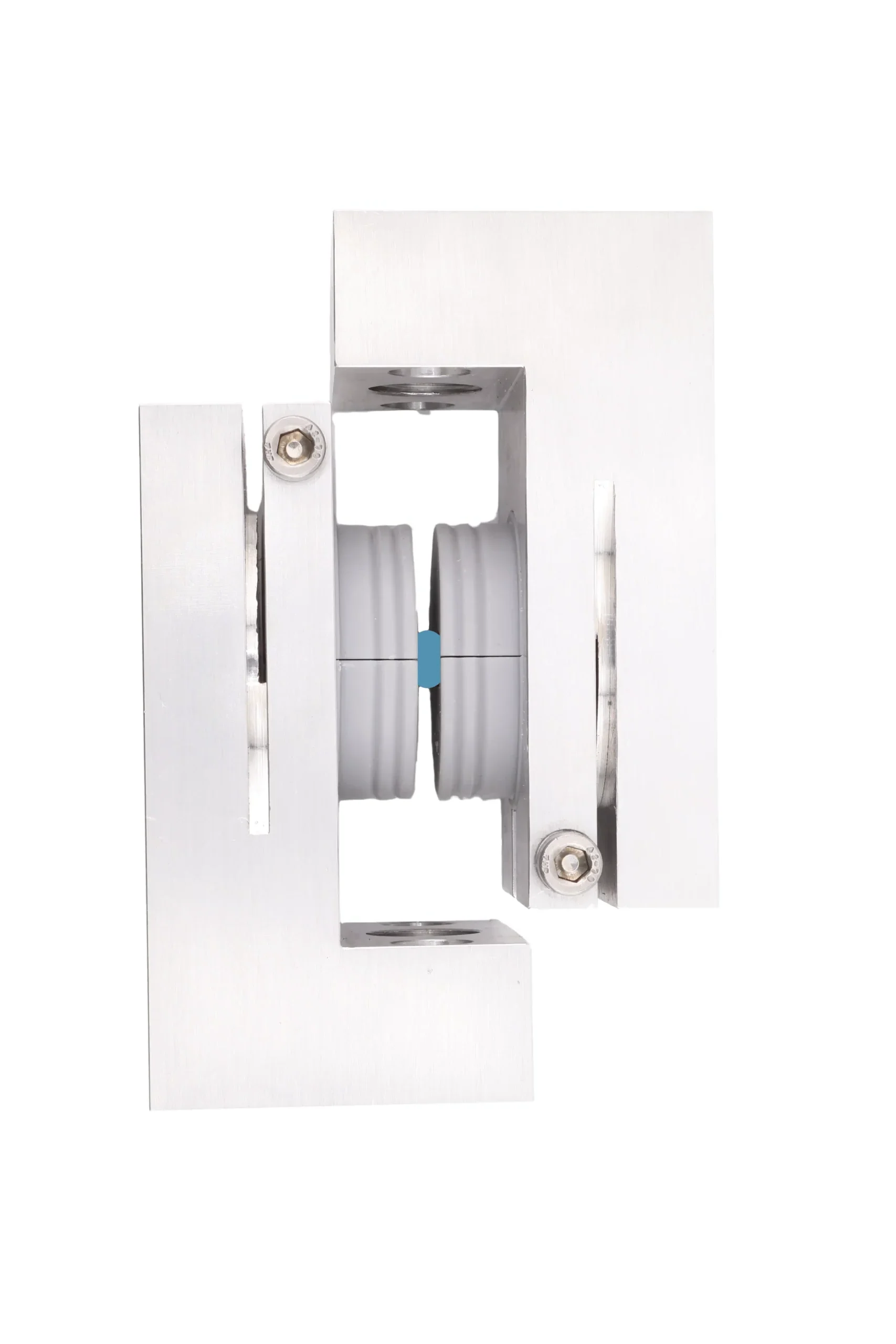
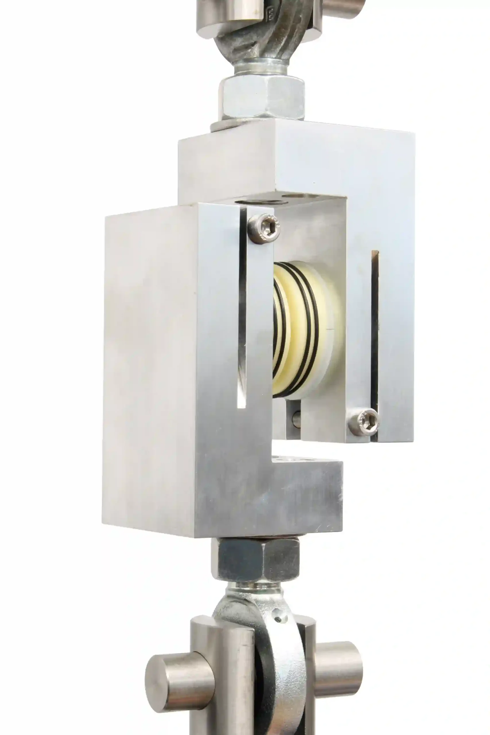
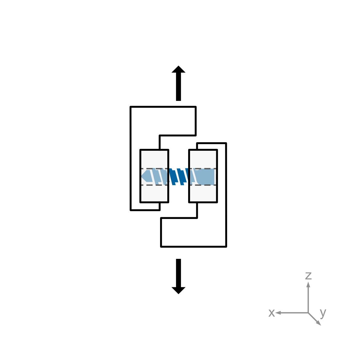
- Static and Dynamic Shear Testing: Applies a purely shear force (F) to the geometric center of the device.
- Static and Dynamic Torsion Testing: Applies a moment (Mz) about the Z-axis (normal to the joint space) through the geometric center. A compressive preload is required for the torsion test.
Measurements: Guidelines are provided for calculating yield force/moment, ultimate force/moment, stiffness, and permanent deformation
Test Setup: The implant is held within device-matched test blocks or a potting medium with a defined 4 mm intra-joint space gap to simulate the motion segment.
Transverse SIJ Fusion Implants (Annex A2)
Test Configurations:
- Static and Dynamic Cantilever Bending: Measures bending strength (yield moment, ultimate moment) and dynamic runout moment (fatigue) by applying a force to the proximal end of the implant
- Axial Pullout Test: Measures the axial pullout strength (maximum tensile force) required to remove the implant from a Grade 20 lb/ft³ polyurethane foam test block.
- Static Torsion Test: Measures torsional yield strength and maximum torque by applying a torsional force in the insertion direction to the specimen.
- Driving Torque Test: Measures the peak insertion torque recorded during the initial four revolutions when inserting a threaded implant into a polyurethane foam block.
Measurements:
- Bending Tests measure the bending stiffness (S), the calculated bending structural stiffness (EIe), the bending yield moment, and the bending ultimate moment. Dynamic bending tests determine the bending fatigue runout moment.
- Pullout Tests determine the axial pullout strength, which is the maximum tensile load the implant can resist before failing or disengaging from the test block.
- Static Torsion Tests measure the torsional yield strength and the maximum torque (torsional peak load) the implant can sustain before failure.
- Driving Torque Tests measure the peak insertion torque required to insert the threaded implant into the test block.
Test Setup:
- Cantilever Bending: The implant is rigidly fixed at its distal tip to an anchoring fixture, leaving an exposed length (L) of no less than 20 mm to serve as the moment arm. The bending force is applied to the proximal end.
- The setups for Pull-out, torsion and driving torque are similar to ASTM F543