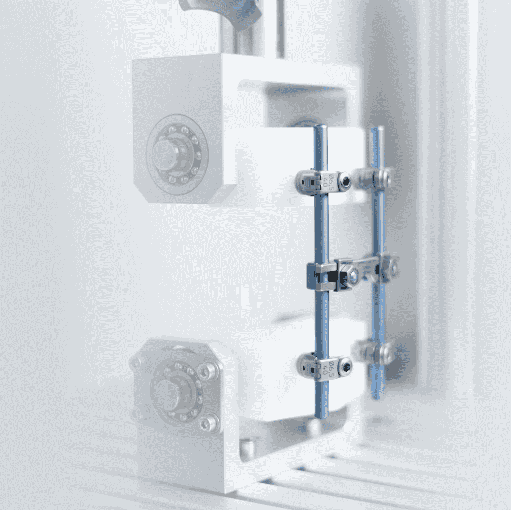


















ASTM F1717: Standard Test Methods for Spinal Implant Constructs in a Vertebrectomy Model.
These test methods cover the materials and methods for the static and fatigue testing of spinal implant assemblies in a vertebrectomy model. The appropriate tests within the standard have to be selected depending on the implant system and its intended spinal location and application method.
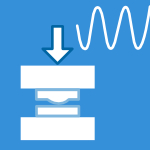
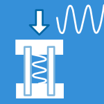
Static and dynamic loading is performed for the worst-case scenario. Load transfer between the resection lines has to be guaranteed by the implant without bone support. Two UHMWPE blocks are used for implant fixation. The dynamic loading is performed at a frequency of 5 Hz and at up to 5 million cycles. In general, six specimens are tested. Regular tests are performed in air at room temperature. The implant material may require test setups simulating body environmental conditions at 37 °C in saline solution.
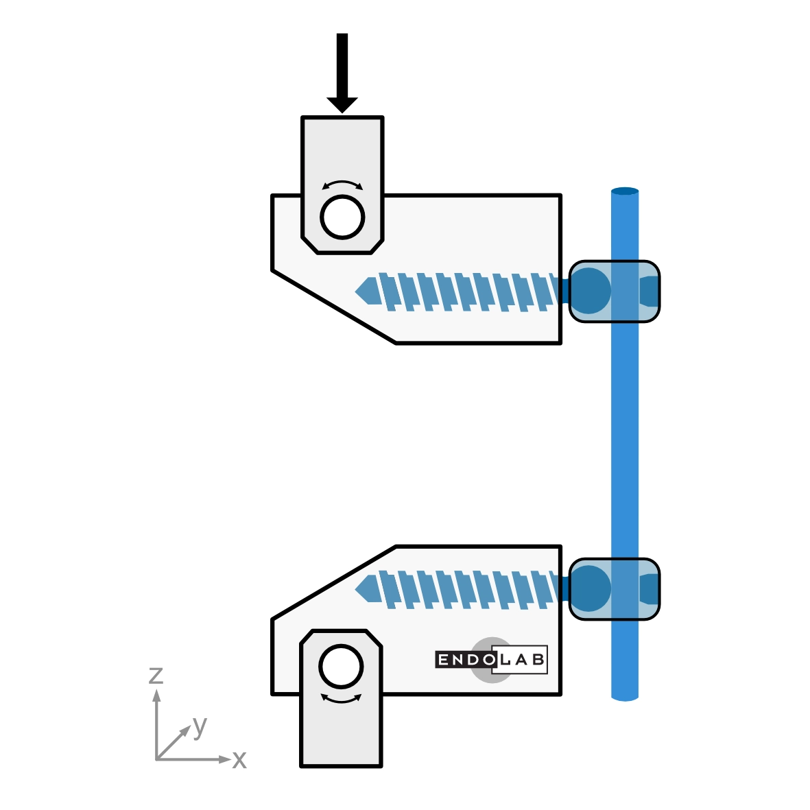
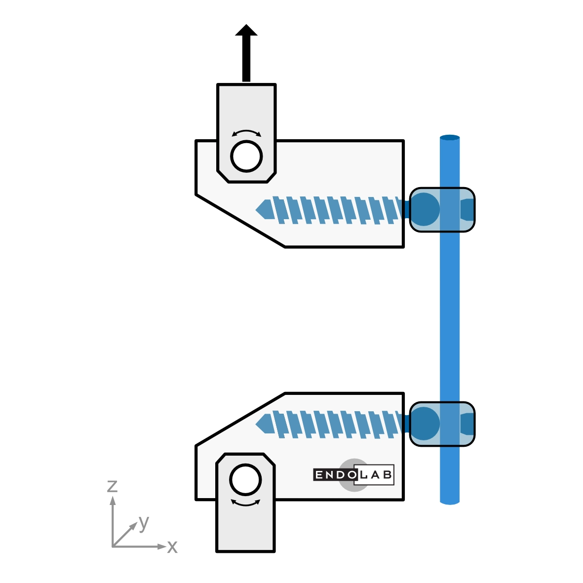
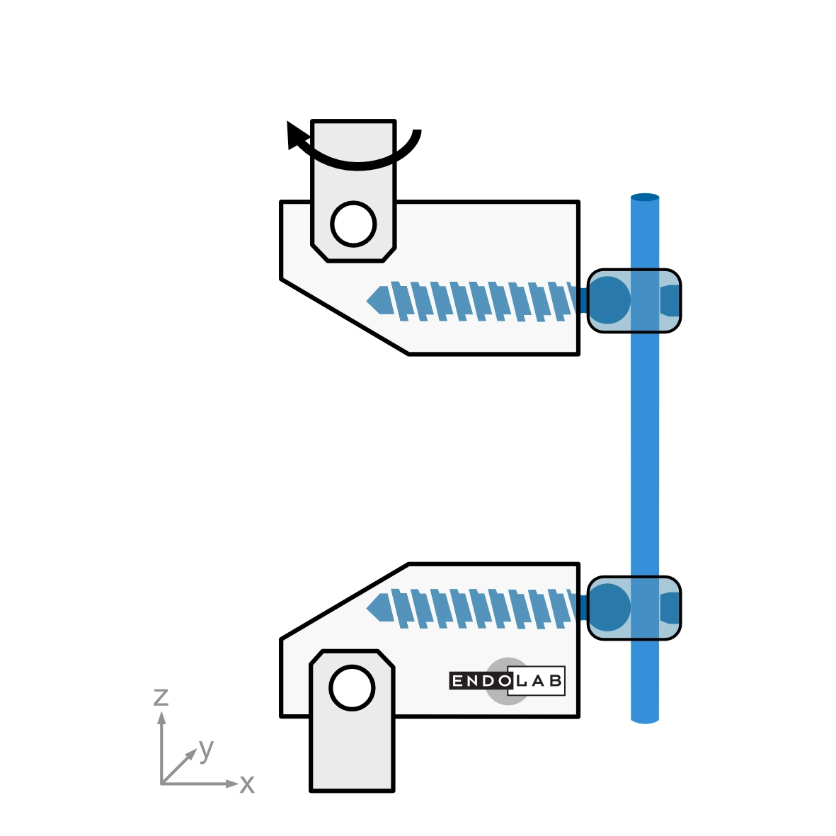
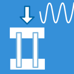
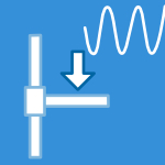
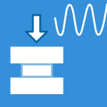
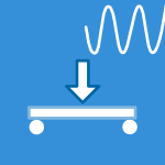
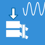
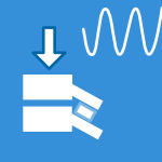
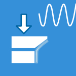
The standard describes the following test procedures: Static and dynamic axial compression bending, static tension bending, and static torsion. This standard is applicable to lumbar and cervical systems.
Read more…
Significance and Methodology
Spinal implant assemblies are made of interacting parts: anchors, rods, plates, screws, hooks, wires, cables, interconnections and sometimes transverse elements. ASTM F1717 evaluates the construct as an assembled system, not just as isolated components. That is important, because weak points often appear where components meet, lock, slide, bend or transfer load.
The test setup uses a simplified load scheme. It does not try to reproduce the full complexity of the spine. Instead, it creates standardized mechanical conditions so that different designs can be compared in a consistent way.
In the vertebrectomy model, the implant bridges a large gap between two UHMWPE blocks. This setup represents a severe condition because the load is carried by the implant construct rather than by an intact vertebral body. For this reason, correct construct setup and orientation are more than small details. They determine whether the test reflects the intended worst-case loading direction.
Test Configurations
ASTM F1717 includes configurations for cervical spinal implant assemblies as well as thoracolumbar, lumbar and lumbosacral assemblies. The intended spinal location influences the geometry of the test setup, including the active length of the longitudinal element and the block moment arm.
The standard describes test configurations for different anchor types and construct designs, including plates, screws or bolts, hooks, wires and cables. The test block design is selected to match the intended spinal location and method of application. Alternate block designs may be used if equivalent performance is demonstrated.
The test method also recognizes that not every spinal construct can be tested in every configuration. The user of the standard must determine which test or combination of tests is appropriate for the implant assembly being evaluated.
Static Testing
Static testing under ASTM F1717 includes compression bending, tension bending and torsion. These tests generate load-displacement or torque-angular displacement curves that are used to determine mechanical properties of the construct.
For compression and tension bending, the reportable values include displacement at 2% offset yield, elastic displacement, yield load, stiffness, ultimate displacement and ultimate load. For torsion, the reportable values include angular displacement at 2% offset yield, elastic angular displacement, yield torque and torsional stiffness.
The static tests help show how the construct behaves as load increases: where the elastic range ends, where yielding begins, how stiff the assembly is and where ultimate failure or maximum load occurs. In simpler terms, the test shows not only how much load the construct can take, but how it gets there.
Fatigue Testing
The compression bending fatigue test is used to evaluate construct behavior under repeated loading. The fatigue test applies a sinusoidal load to the spinal construct under constant load amplitude control. The maximum cycle rate is 5 cycles per second.
Fatigue testing continues until the construct fails or reaches run-out. ASTM F1717 defines run-out as reaching 5,000,000 cycles without failure. The results are used to establish a relationship between compression bending load and number of cycles to failure.
Initial fatigue load levels may be selected based on experience. If no such experience is available, the standard describes starting points based on percentages of the static yield load. The fatigue evaluation can then be used to generate a fatigue curve and determine the maximum run-out load.
Test Environment
ASTM F1717 recommends initial fatigue testing under dry ambient room conditions for consistency. The standard notes that simulated body fluid, saline, water or lubricants may affect relative performance, for example through fretting, corrosion or lubrication of interconnections.
Some implant materials may require test setups that simulate body environmental conditions, such as 37 °C in saline solution.
Samples and Handling
All components used in the spinal implant assembly are previously unused parts. Implants are not retested. UHMWPE test blocks are used for one test only, and where alternate block designs with UHMWPE inserts are used, the inserts are replaced after each test.
Static tests generally use a minimum of five samples. Fatigue testing uses a sample strategy that supports development of a fatigue curve and identification of run-out behavior.
After testing, constructs are labeled, maintained and documented according to good laboratory practice. The construct should not be disassembled unless disassembly is needed to evaluate failure surfaces, interconnections, corrosion or loosening surfaces. Photographs are taken before disassembly.
Failure Analysis and Documentation
ASTM F1717 places strong emphasis on documenting what happened during the test. For static tests, the report includes load-displacement or torque-angular displacement curves, test values, means and standard deviations, and a description of failures, deformations and surface changes.
For fatigue tests, the report includes the test environment, waveform, test frequency, sample size, load levels, cycles to failure and maximum run-out load. Failure descriptions should include initial and secondary failures, failure modes, deformation of components, fretting, loosening of interconnections and surface changes.
This documentation is where the test becomes especially useful. A single maximum load value is helpful, but the failure mode often tells the more interesting story: Did the rod deform? Did an anchor loosen? Did a connection slip? Did fretting appear at an interface? ASTM F1717 makes space for those observations.
Testing at EndoLab
EndoLab performs static and dynamic testing of spinal implant constructs according to ASTM F1717. The test is selected according to the implant system, the intended spinal location and the intended method of application. With ASTM F1717, the spinal construct is placed in a clear mechanical situation: bridge the gap, carry the load, and show how the assembly behaves. EndoLab supports this process with controlled setup, precise loading, careful documentation and detailed evaluation.