
















ASTM F2028: Standard Test Methods for Dynamic Evaluation of Glenoid Loosening
ASTM F2028 provides separate dynamic test methods for evaluating the fixation of anatomic and reverse glenoid components. Both methods quantify component displacement before and after cyclic loading to assess resistance to loosening and support comparisons between implant designs.
The standard covers:
- Cemented monolithic or modular anatomic glenoid components
- Uncemented reverse glenoid baseplates fixed with screws
- Selection and justification of worst-case test constructs
- Static displacement measurements before and after dynamic loading
- Dynamic rocking or articulation under compressive loading
- Documentation of displacement, test observations, and construct failure
ASTM F2028 is intended primarily for detecting potential design problems and comparing or ranking devices. It does not define a universal acceptance limit for glenoid displacement.
Read more…
Scope and application
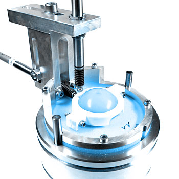
For anatomic shoulder systems, the method measures rocking or pivoting of the glenoid component after the humeral head has been repeatedly displaced toward opposing glenoid rims. Testing may be performed in the superior-inferior direction, anterior-posterior direction, or another justified direction. Motion is quantified by measuring displacement at the component edges.
For reverse shoulder systems, the method evaluates the initial fixation of the glenoid baseplate before and after dynamic articulation with the mating humeral liner. Displacement is measured under combined axial compressive and shear loading.
The reverse shoulder method evaluates short-term mechanical fixation. It does not assess the contribution of biological fixation or the long-term effects of implant integration.
Test specimens and worst-case selection
A representative worst-case construct must be selected and justified. Relevant variables can include component size, articular geometry, augments, eccentricity, fixation features, screw type, screw dimensions, screw angulation, screw position, press fit, glenosphere thickness, glenosphere diameter, and center-of-rotation configuration.
All glenoid components must be in their final manufactured condition. Plastic components are sterilized according to the manufacturer’s specifications for clinical use. Implantation into the bone substitute is performed using the manufacturer’s surgical technique and instrumentation.
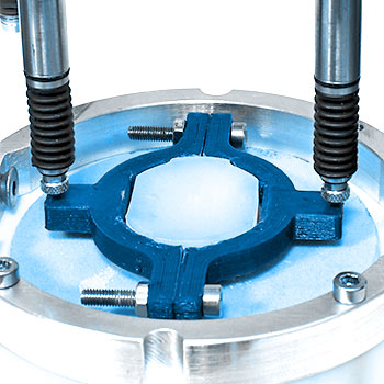
A bone substitute representing glenoid cancellous bone is required. When rigid polyurethane foam is used, ASTM F2028 recommends Grade 20 material conforming to ASTM F1839. Other bone substitutes may be used when their selection is justified. Test and reference implants must be evaluated under identical conditions.
Anatomic glenoid loosening test
The anatomic method applies to cemented glenoid components. The component is implanted into the bone substitute with bone cement, and testing begins after the cement has cured.
At least n=3 specimens are tested dynamically. At least n=3 additional specimens should be used to determine the subluxation translation. The mating humeral head must reproduce the radius or radii and material of the clinical implant.
The test sequence includes:
- Experimental determination of the subluxation translation in both loading directions
- Measurement of glenoid edge displacement before dynamic rocking
- Dynamic translation of the humeral head to 90% of the average subluxation translation
- Measurement of edge displacement after dynamic rocking, unless displacement is monitored continuously
A nominal axial compressive load of 750 N is applied perpendicular to the glenoid plane. Edge displacement is measured with the humeral head at the glenoid origin and at 90% of the subluxation translation in each direction.
Dynamic testing is performed in water maintained at 37 °C ± 2 °C. For large translations, the standard gives 0.5 Hz as an example frequency and limits the frequency to a maximum of 3 Hz. A maximum of 100,000 cycles is suggested, although testing may continue to a higher cycle count when required by the test objective.
For symmetrical designs, the cyclic path should produce comparable peak loading at the two opposing rims. Augments, asymmetrical fixation, or other design features may make another test direction more severe, so the selected axis must be justified.
Reverse glenoid loosening test
The reverse shoulder method applies to uncemented glenoid baseplates fixed into the bone substitute using screws. A minimum of three specimens is required. A new humeral liner is used for each test, with the same articular radius or radii and material as the clinical implant.
When evaluating the limits of performance, the construct includes the minimum number of the worst-case size and type of screw permitted by the surgical technique. Screw positioning, augments, baseplate geometry, lateralization, and eccentricity are considered when selecting the configuration.
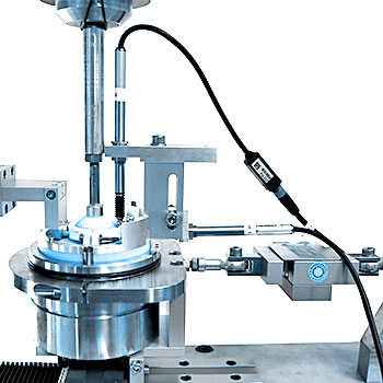
Initial baseplate displacement is measured under an axial compressive load of 430 N and a shear load of 350 N. Displacement is determined in the directions of both loads. Measurements may be taken directly from the baseplate or from the assembled baseplate and glenosphere.
For the dynamic portion, the glenosphere is connected to the baseplate and articulated against the humeral liner. A nominal axial compressive load of at least 750 N is applied through the center of rotation. The reverse glenoid component is rotated:
- For 10,000 cycles
- Through an arc of at least 45°
- Typically along the superior-inferior axis
- At a recommended frequency of 0.5 Hz, with a maximum of 1.0 Hz
Testing may be continued beyond 10,000 cycles when appropriate. The test is terminated if the construct dislocates, disassociates, or otherwise fails.
Dynamic articulation may be performed in air at room temperature with appropriate cooling or in a lubricated environment. Because lubrication influences frictional torque and loading at the bone-implant interface, the selected environment must be controlled and justified. Components tested in air must cool to room temperature before post-dynamic displacement measurements are made.
Displacement measurement and test directions
ASTM F2028 permits suitable contact or non-contact techniques for measuring component motion, including displacement transducers and digital image correlation. The method must resolve displacement in the directions relevant to the selected loading configuration.
For noncircular reverse baseplates, shear loading and displacement measurement should generally address both major and minor axes. Asymmetrical constructs may require measurements in multiple loading directions. The selected axes must account for features such as augments, eccentric glenospheres, and screw patterns.
Pre- and post-dynamic measurements are repeated to confirm measurement repeatability. Test and reference devices should use the same setup, environment, measurement conditions, and bone substitute so that the resulting ranking remains meaningful.
Evaluation and reporting
The principal results are the displacement measurements obtained before and after dynamic loading. For anatomic glenoids, the report includes subluxation loads and translations together with edge displacement at the origin and at 90% of the subluxation translation. For reverse systems, displacement in both the axial compressive and shear directions is reported at the applicable peak loads.