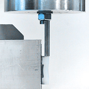

















ASTM F1829: Standard Standard Test Method for Static Evaluation of Glenoid Locking Mechanism in Shear.
ASTM F1829 specifies a method for determining the static shear disassembly force of the locking mechanism in a modular anatomic glenoid component. It is intended to be used as a design validation and for comparison with other prostheses. The method evaluates how effectively the locking mechanism retains the insert when subjected to shear loading in two directions:
- Inferior to superior
- Anterior to posterior
A minimum of n=5 samples is tested in each direction per device. The principal results are the maximum load, the load-displacement response, and the observed failure mode.
ASTM F1829 supports comparisons between locking-mechanism designs tested under equivalent conditions. It does not reproduce every physiological loading condition and cannot be used to predict clinical performance directly.
The test set-up must be designed to allow for lateral displacement of the insert under load. Rigid fixation of the loading fixture to the load actuator will result in wrong (higher) loads. Depending on the insert fixation design, some implants might not be suitable for testing according to ASTM F1829.
Read more…
Scope and application
The test method applies to modular anatomic glenoid components with a separate articular insert and backing. The components may incorporate metal alloys, polymers, or composite materials in different combinations.
Testing can help manufacturers assess the effects of design, material selection, manufacturing processes, and component configuration on resistance to static shear disassembly. The method is intended primarily for controlled in vitro comparison of metal-backed or composite-backed glenoid locking mechanisms.
Test specimens
Articular inserts must be representative of final manufactured implant-quality components. A new insert is used for every test.
The glenoid backing may be either the final implant or a simplified test component incorporating the exact locking mechanism intended for the final implant. Its materials, surfaces, and manufacturing processes, including applicable heat treatment, should represent the finished product.
Components should be sterilized according to the manufacturer’s recommendations when sterilization could affect the test result.
The selected component size and test configuration should represent an appropriately justified condition. ASTM F1829 recommends considering the potential clinical and design-related failure modes when identifying the worst-case size and loading condition.
Loading directions and sample quantities
Separate testing is performed with the load applied in the two specified anatomical directions:
- At least five samples with loading from inferior to superior
- At least five samples with loading from anterior to posterior
The test fixture is arranged so that the line of load application is parallel to the intended axis of the implant for the direction under evaluation. For asymmetric components, the relationship between the component geometry and the test orientation must be clearly defined.
Static shear test procedure
The articular insert is properly assembled into the glenoid backing before the assembly is mounted in the test machine. A blunt-edged applicator applies load to the insert at a defined offset from the edge of the locking mechanism.
Loading is applied at a constant displacement rate, which is recorded for the test. ASTM F1829 gives 25.4 mm/min as an example.
Testing is normally conducted in air at room temperature. A simulated physiological environment may also be used when its temperature, humidity, fluid, and other relevant conditions are documented.
The test continues until one of the following occurs:
- The insert disengages from the glenoid backing
- The disengagement force reaches a maximum and subsequently decreases
- The insert undergoes gross deformation without dislocation
Load and displacement are recorded throughout the test. The glenoid backing is visually inspected for damage after each test run.
Results and evaluation
The primary quantitative result is the maximum load reached during the test. Load-displacement curves provide additional information about the mechanical response of the insert and locking mechanism.
The observed failure mode is documented for every specimen. Depending on the design, this may involve insert disengagement, declining resistance after the maximum load, or gross deformation without complete dislocation.
Interpretation and limitations
ASTM F1829 does not specify a universal acceptance value for locking strength. Results are used to characterize a device or compare designs under consistent test conditions.
The method addresses static shear loading only. It does not evaluate every loading or failure mode that a glenoid component may experience. The standard notes that fatigue may be more likely to cause clinical disassembly of some locking mechanisms, so additional evaluations may be needed based on the implant design and risk assessment.
No precision or bias statement is provided because glenoid designs vary widely and no standard reference implant is available. Results should therefore be interpreted in relation to the tested design, configuration, environment, and documented test conditions.