




























ASTM F1820: Standard Test Method for Determining the Forces for Disassembly of Modular Acetabular Devices
This test method covers three different tests to determine the mechanical strength of the fitting between the acetabular shell and liner.
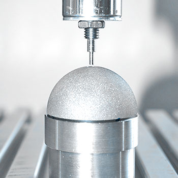
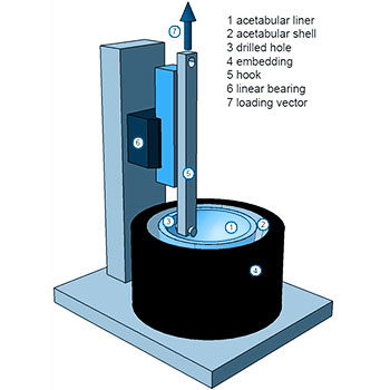
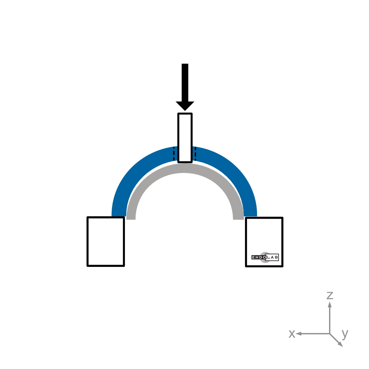
The push-out test determines the axial locking strength of the acetabular liner within the acetabular shell.
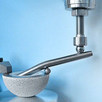
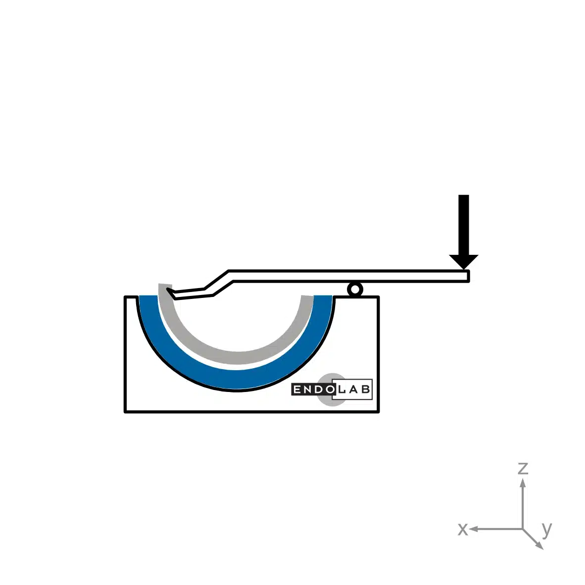
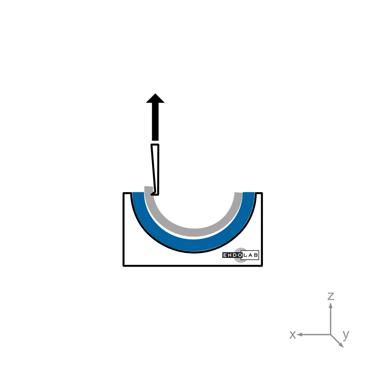
The offset pull-out or lever-out disassembly test determines the resistance of the locking mechanism to edge forces. They could occur when the neck of the femoral stem impinges on the edge of the acetabular liner.
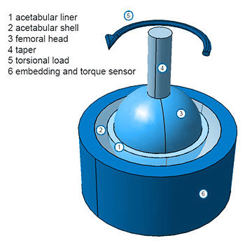
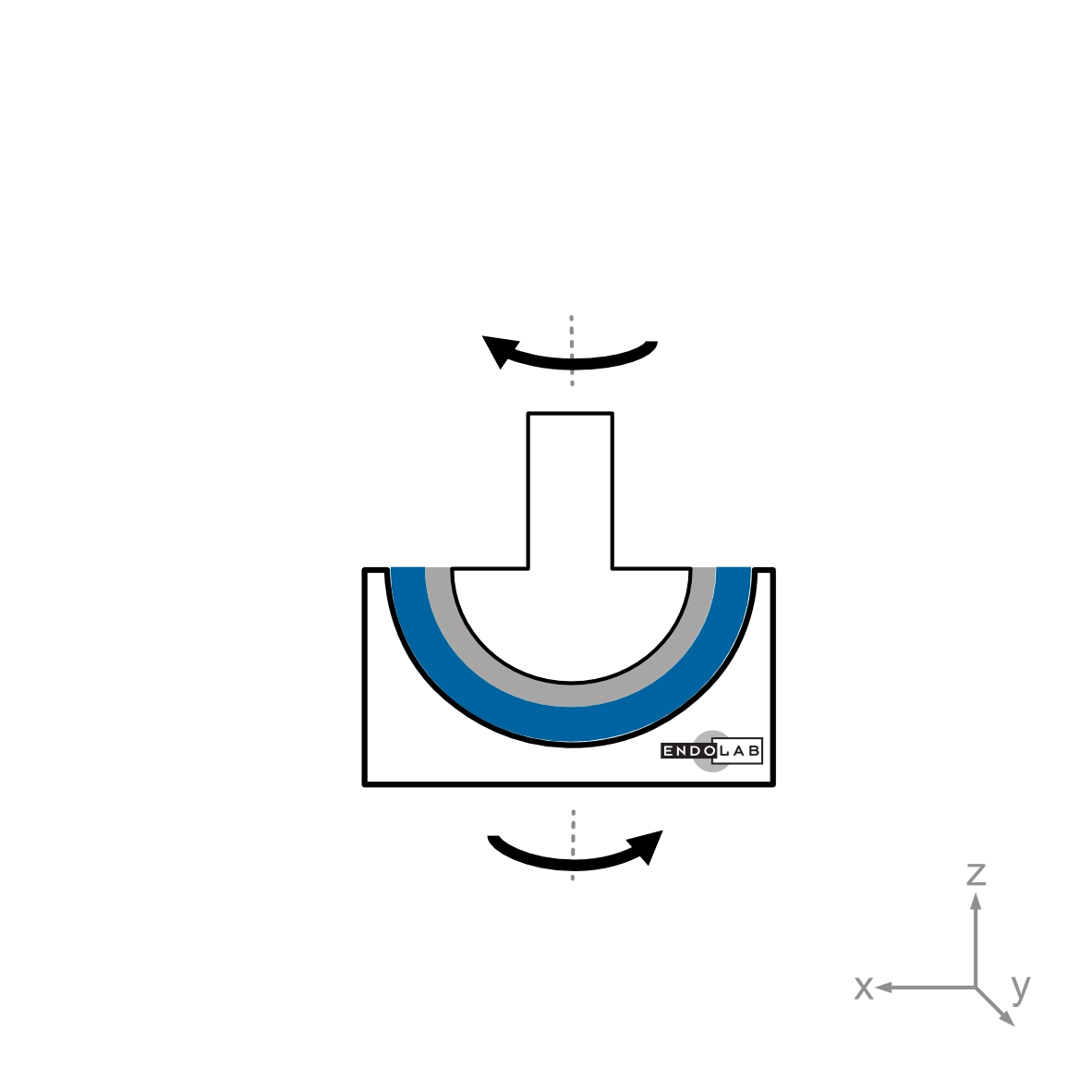
The torque-out test determines the resistance of the locking mechanism against torsional forces.
EXECUTIVE SUMMARY
ASTM F1820 provides comparative test methods for evaluating the attachment strength between the liner and shell of a modular acetabular device. The standard addresses three loading conditions:
- Axial disassembly or push-out
- Offset pull-out or lever-out disassembly
- Torque-out disassembly
These tests characterize different aspects of the locking mechanism. They do not reproduce physiological loading conditions and do not establish a minimum acceptable disassembly force or torque.
Read more…
Purpose of the test
ASTM F1820 assesses the integrity of acetabular liner locking mechanisms under three types of loading:
- Axial loading along the polar axis
- Edge-related loading associated with liner impingement
- Rotational loading of the liner within the shell
The results can support comparisons between designs, sizes, materials, or locking concepts. Implant size and locking mechanism geometry must be considered because both can influence the measured force or torque.
Devices covered by ASTM F1820
The test method applies to modular acetabular devices consisting of an acetabular shell and a separate liner. It covers:
- Polyethylene and hard-bearing liners
- Dual mobility and constrained liner applications
- Locking features incorporated into the shell and liner
- Designs that use additional locking components, such as rings or screws
The method may not be appropriate for every implant design. The materials, locking principle, component geometry, and intended application should be considered when defining the test program.
Test specimens
The specimens must be representative of implant-quality products. This includes sterilization or thermal processing that could affect material properties or component geometry.
Important specimen requirements include:
- A minimum of n=5 shell-liner assemblies for each test method
- Random pairing of shells and liners unless another approach is reported
- Justification of the sample size when results are used for statistical comparisons
- Documentation of the device size, materials, and lot information
A partially finished shell or permanent fixture block may replace the complete shell when its internal material, surface finish, locking mechanism, geometry, and manufacturing conditions are identical to those of the finished product.
Assembly conditions
Before testing, the liner is assembled into the shell with a peak force of 2,000 N applied along the polar axis. Alternatively, the assembly method specified in the manufacturer’s surgical technique may be used when it is reported and justified. For polyethylene liners, the same shells may be used for all three evaluations if they remain undamaged and the integrity of the locking mechanism has not been affected.
Axial disassembly or push-out
The axial disassembly test measures the force required to release the liner along the polar axis. The shell is supported continuously without deformation while the liner remains free to disengage. An axial force is applied to the liner through the shell, typically through an opening at the shell apex.
The test determines:
- The maximum force required to disengage the liner
- The failure mode of the specimen
- Whether liner damage occurs before the locking mechanism releases
The displacement rate must not exceed 0.04 mm/s for hard-bearing liners with a taper-locking mechanism or 0.85 mm/s for polyethylene liners. Additional testing or an adapted load applicator may be required if a thin polyethylene liner is punctured or severely damaged before the locking mechanism releases.
Offset pull-out or lever-out disassembly
This evaluation assesses resistance to edge-related loading. Such forces can occur when the femoral neck impinges on the liner rim and tends to lift the opposite edge of the liner from the shell.
The test may use:
- An offset pull-out arrangement
- A lever-out arrangement
- A prepared attachment point in the liner
- A bonded fixture for suitable hard-bearing liners
The specimen preparation must not interfere with the locking mechanism. The maximum force required to disengage the liner is recorded. When a lever arrangement is used, the measured test-machine force is converted to the force acting on the liner using the lever-arm dimensions.
Torque-out disassembly
The torque-out test evaluates the anti-rotation features of the locking mechanism. The shell and liner are aligned with the torsion axis of the test system, and torque is transferred to the liner through a suitable test interface.
Central test conditions include:
- A compressive load of no more than 25 N during torque application
- A maximum torque rate of 6°/s for polyethylene liners
- A maximum torque rate of 0.05°/s for hard-bearing liners
- Recording of torque and rotational displacement
The peak torque is reported as the torque-out value. The test normally ends when the torque decreases by more than 10% from the preceding peak.
Results and reporting
The test report includes:
- Maximum disassembly force or torque for each specimen
- Failure mode for each valid or invalid test
- Device designation, dimensions, materials, and lot information
- Assembly method and relevant test configuration
- Orientation of the liner and shell when their axes are not coincident
- Lever dimensions and calculated liner force for lever-out testing
Material failure can occur before the locking mechanism releases, particularly during push-out or offset testing of thin liners. Complete fracture or severe deformation before disassembly generally invalidates the individual test because the locking strength has not been fully measured.