




































ASTM F2009: Standard Test Method for Determining the Axial Disassembly Force of Taper Connections of Modular Prostheses
ISO 7206-10: Determination of resistance to static load of modular femoral heads
These tests are performed to determine the force required to disassemble the taper connections of modular prostheses.
The ASTM F2009 standard applies to all tapered connections of modular prostheses, such as total or partial hip or shoulder prostheses. The ISO 7206-10 standard is specific to hip femoral heads and describes the method to establish the tension load to disassemble modular head systems.
EXECUTIVE SUMMARY
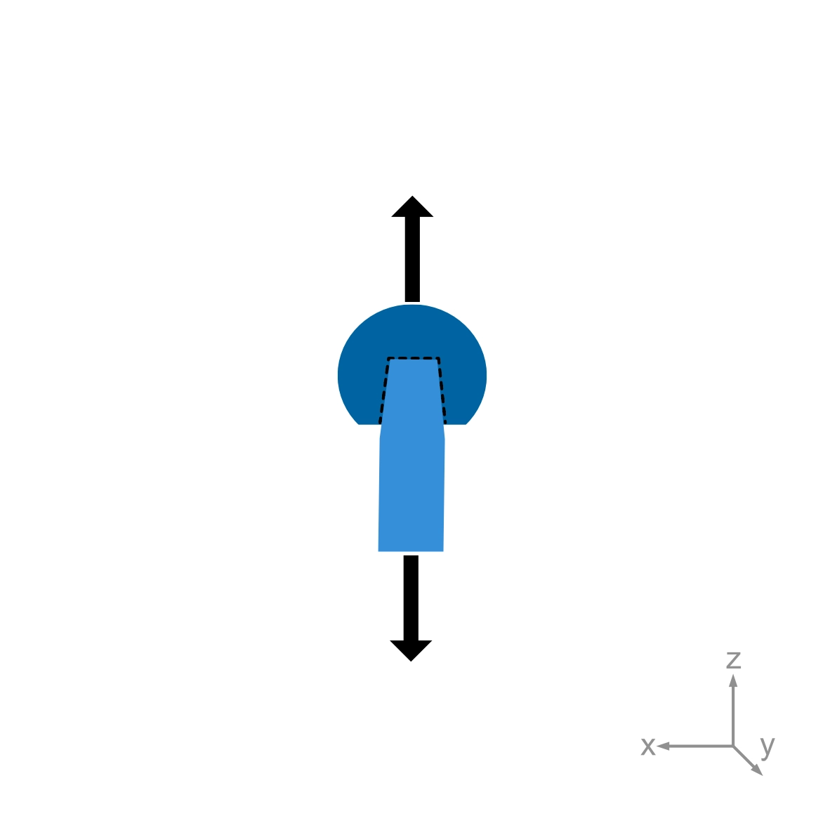
The ASTM F2009 test evaluates the mechanical stability of a modular taper connection by measuring the force required to pull the assembled components apart.
Before testing, the taper components are cleaned and assembled under defined conditions. ASTM F2009 specifies a controlled axial assembly force of 2 kN.
The assembled specimen is then subjected to an axial tensile load until the taper connection separates. Force and displacement are recorded during the test, and the maximum force required for separation is determined.
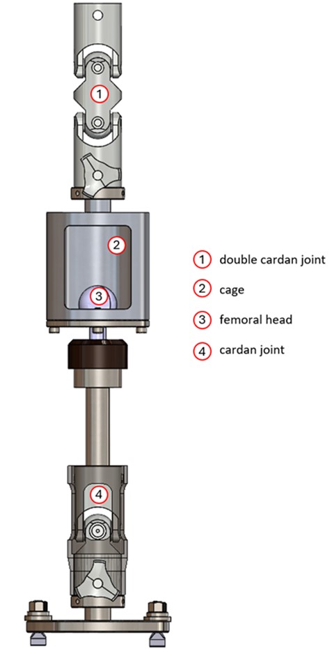
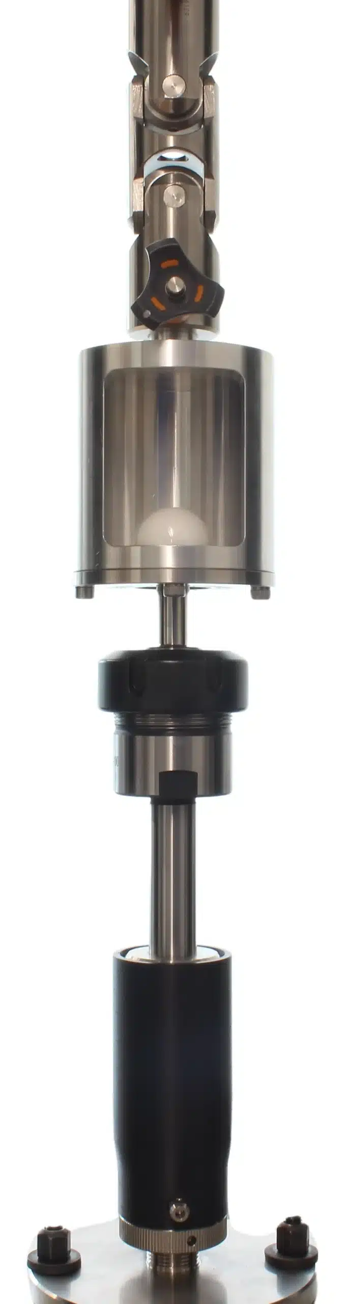
Particular attention is paid to correct alignment of the specimen and fixtures so that the load is introduced as axially as possible and the influence of bending or transverse forces is minimized.
Read more…
Purpose of the test
The purpose of ASTM F2009 is to assess the axial locking strength of modular taper connections under reproducible laboratory conditions.
The method was developed primarily for metal and ceramic heads assembled onto metal tapers, but it may also be applicable to other modular implant designs and material combinations.
It is particularly suitable for comparative investigations, for example when evaluating:
- different taper designs
- different material combinations
- different component variants
When interpreting the results, the geometry and locking mechanism of the tested components should also be taken into account.
Because actual loading conditions during surgery and in the body can vary considerably, ASTM F2009 represents a simplified laboratory model rather than a simulation of every possible clinical loading situation.
Test specimens
Testing can be carried out using finished implant components or representative test specimens.
When simplified specimens are used, the taper geometry and material should correspond to those of the finished implant so that the tested connection is representative of the actual device.
ASTM F2009 specifies a minimum of five taper assemblies for determination of the axial disassembly force.
For comparative testing, the specimens should be selected and prepared consistently. Comparable component configurations within the individual test groups help ensure that differences in the measured disassembly force can be attributed as clearly as possible to the design or material being investigated.
Test procedure
Before assembly, the taper surfaces are cleaned to remove debris and surface contamination.
The male and female taper components are assembled in a testing machine using a controlled axial force. In accordance with ASTM F2009, a peak assembly force of 2 kN is applied along the axis of the taper connection.
The subsequent disassembly test involves:
- positioning the assembled specimen in a suitable fixture
- applying an axial tensile load
- continuously recording force and displacement
- continuing the test until the taper connection disengages
The maximum tensile force required to separate the components is determined as the axial disassembly force.
Careful specimen alignment and suitable fixturing are important to ensure that the measured force reflects the axial strength of the taper connection and is not unnecessarily influenced by off-axis loading.
Evaluation
The primary result of the ASTM F2009 test is the maximum force required to separate the taper connection.
For each test group, the individual disassembly forces are evaluated together with statistical parameters such as the mean value, range and standard deviation.
The results can be used to compare different taper designs, materials or component configurations under defined laboratory conditions.
The test report also documents the relevant specimen configuration, assembly conditions and test setup so that the results can be interpreted in the context of the tested implant system.